
There are major efforts underway to “decarbonize” the GB rail network. One way of pursuing this goal is to reduce traction energy costs which would contribute to decarbonization either directly through the reduction in fossil fuel use, or indirectly through the reduction in the use of electricity produced from non-renewable sources. In this post, I will attempt to show that the train aerodynamic drag reduction due to the use of slab rather than ballasted track may result in significant fuel and energy savings for an entire train fleet that would contribute to the decarbonization agenda and that could radically change the overall business case for the installation of slab track, which is currently only used in specific circumstances. It will be seen that the argument is very speculative in places, but perhaps strong enough to warrant further investigation. We begin in the next section with an introduction to train resistance.
Train Resistance
The specification of train resistance is required for the assessment of energy consumption, train timing etc. Now train resistance is, very broadly, composed of mechanical (rolling) resistance and aerodynamic resistance, and is conventionally described by the Davis equation given in equation (1).

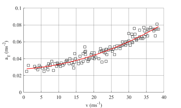
Here v is the train speed and a, b and c are constants. The first two terms are taken to be the mechanical resistance, and the last term is taken to be the aerodynamic resistance. The aerodynamic resistance is thus proportional to the square of train speed and becomes progressively more important as train speed increases. The parameters a, b and c are usually obtained from coast down tests on (ideally) straight, level section of track, in which trains coast from top speed to zero and acceleration, speed and distance are measured. A quadratic curve is then fitted to data. Typical examples of tests sites in the UK are given in figure 1 and a typical set of results in figure 2. Note that this figure and most of those that follow are taken from the recent book “Train Aerodynamics – Fundamentals and Applications” by myself and a number of colleagues. Note also that it is also possible to estimate the aerodynamic component of resistance from wind tunnel tests and CFD calculations, but there are significant technical issues (mainly due to the inability of both techniques to model full length trains) and thus in what follows we consider only data from full scale measurements.
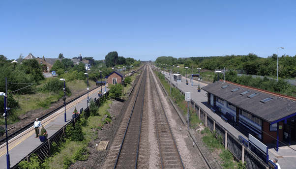
Thirsk to Northallerton 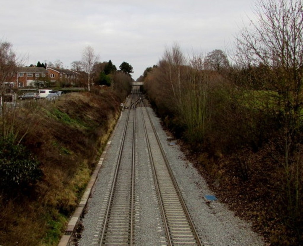
Lickey Incline
Drag coefficient
The coefficient c is related to the aerodynamic drag coefficient CD by the simple expression of equation (2).

Here A is the frontal area of the train and r is the density of air. The drag coefficient for a wide range of trains is shown in figure 3 (from ???).

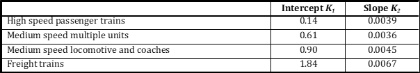
Very broadly, for any individual train class, the drag coefficient in linearly proportional to train length, and can be represented by the simple form of equation (3).

Here L’ is an effective train length (the length of the train minus the length of the nose and tail sections) and p is the wetted perimeter of the train envelope. The values of the parameters K1and K2 are given in table 1 for the train types shown in figure 3.
Breakdown of Aerodynamic drag
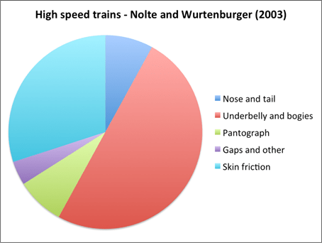
Figure 4 shows how the components of aerodynamic drag for high speed trains from the work of two different authors. Whilst there is some variability between the results it can be seen that the drag of the underbelly and bogies contributes 20 to 50% of the overall drag and skin friction drag on the train side and roof contributes 30% to 40%. An important point to appreciate is that the underbody drag includes drag due to the track roughness – energy needs to be used to overcome the aerodynamic resistance of the track itself. This point does not seem to have been well appreciated in the past.

Referring back to equation (3), K2 is a friction coefficient for train, combining theeffect of skin friction on side and roof and bogie and underbody drag. As can be seem from figure 3, values of 0.004 are typical for high speed trains (but note the quality of fit is not terribly good).
Friction coefficients can be obtained directly from measurements of the velocity profile on the side and beneath the train and then fitting of logarithmic profile to the data. This process is somewhat difficult and subjective, but has nonetheless been attempted by a number of authors in the past. Table 2 shows the values for skin friction on the side of the train that have been obtained, and table 3 shows values for the underbody of trains.

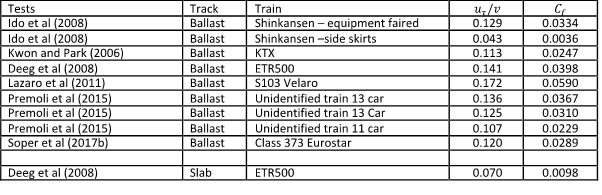
Typical values of the former are 0.0015 and typical values for the latter for ballasted track are 0.03. The higher values for underbody coefficient are of course to be expected because of the roughness of the train underbelly. For slab track the one set of data available gives a significantly lower value of the underbody friction coefficient of 0.01.
Synthesis
If we assume that, for high speed trains, skin friction values of 0.0015 and underbody drag of 0.03 and assume that the former acts over 90% of the wetted perimeter and the latter over 10% these weights give a value of K2 of 0.00435 which is consistent with drag compilation value from table 1 of 0.004 and result in a drag coefficient of 1.4 for a 200m high speed train. If underbody drag reduced to 0.01 by use of slab track, the same calculation leads to drag coefficient of 0.81 – a staggering 40% decrease. A rule of thumb that is often applied is that a drag coefficient reduction of x% results in an energy saving of 0.4x% suggests 40 x 0.4 % which suggest a potential reduction in fuel use of 16%.
Now many assumptions have been made in the above analysis, perhaps the most significant being the value of friction coefficient for slab track, which is based on one set of experimental results only. Thus the argument that significant fuel cost reductions might be a possibility through the use of slab track more widely, is at best suggestive but I would suggest merits further investigation. The question arises as to whether such energy savings have the potential to change the business case for slab track, which is in general only currently used for very specific situations such as tunnels, poor ground conditions etc. I would thus suggest a preliminary investigation that addresses the question of what reduction in drag coefficient would actually be required to change business case for slab track? As both infrastructure and trains would be involved, a system approach would be required here. If further investigation of the business case shows that it is worth pursuing these ideas, the next stage would be to conduct coastdown tests with the same train over ballasted and slab track. A long straight level section of slab track would thus be required. Does such a section of track exist in the UK?

One thought on “Reducing train aerodynamic resistance through the use of slab track”